| HOW
TO INSTALL THE MT19 REAR AXLE AND SPROCKET MODIFICATIONS
So, you
want to take one of those exotic trips in your MT19 but have heard
stories about rear axles breaking. The last thing you want is
to have your axle break halfway to Tumbler Ridge or in the
middle of the Copper Canyon. What to do?
Well,
in recent years several NARCOA members have researched the cases
of broken MT19 rear axles and determined that the original installation
design lead to excessive flexing of the axle under certain conditions,
which ultimately caused axle failure.
In an
effort to correct the problem, a second chain idler sprocket
was mounted on a redesigned bracket that eliminates much of the
excessive axle flexing by changing the path of the drive chain.
This modification is described in the Nov./Dec. 2000 SETOFF in
detail. We now produce this special bracket.
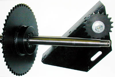
A new
rear axle made of 4150 HT turned, ground and polish steel which provides much more strength than the original
axle has recently become available. Since most axle failures
occurred at the keyway which is the weak point of the original
axle design, it has been eliminated by using a U.S. Tsubaki “PowerLock”
keyless sprocket. The details for the axle and sprocket were published
in the Mar./Apr 2001 SETOFF.
Anyone
contemplating a rear axle replacement should read both these
articles. A number of cars have been modified and have run long
distances during the 2001 season with no failures.
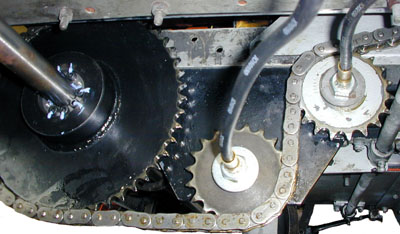
In order
to install the dual idler bracket, you will have to reverse the
center axle bearing so that the support bolts are behind the rear
axle. (A few later cars were built this way by Fairmont in an
apparent attempt to solve the breakage problem) You must remove
or at least partially remove the rear axle in order to reverse
the bearing block as just flipping it 180 degrees on the axle
will not work due to the shape of the casting. If you are going
to install the bracket, you might as well change the axle at the
same time, since the rear axle may be near the point of failure
and your going to do almost all the work anyway.
A few
special tools make the job much easier. You will need a
1-5/16” socket for the axle nuts. Probably the most difficult
part of an axle change is removing the wheel hubs from the axle.
Our hub puller works extremely well. It makes hub removal as easy
as removing a wheel. A turntable makes the job much easier by
allowing easy access under the car. Be sure the car is also blocked
in position so that it cannot fall on you before going underneath.
If you don’t have a turntable, you will need to find a way to
lift the car while leaving the rear wheels and axle free to turn.
A few
things to think about before beginning. Check the gauge of the
car by placing a tape measure through the “spoke” holes in the
wheels and measuring from wheel face to wheel face. Fairmont calls
for a dimension of 62-3/4” and cautions that the front and rear
axle should be the same. If the rear axle is under gauge, you
may want to change the insulators while you have the hubs off.
If the front is undergauge, and you don’t want to pull the hubs
to change the insulators, our shims can be ordered in 1/16” and
1/8” inch thicknesses to set the wheels to proper gauge and match
the rear wheel gauge.
Before
you lift the car from the ground, break the wheel nuts, axle nut
and the four Allen headed screws on the rear sprocket loose so
the can easily be turned. Like changing a tire on your car, it
is much easier to fight a seized nut on the ground. After
the car has been lifted, hopefully using a turntable, make sure
it cannot fall by blocking, jacking etc. as needed, then remove
the drive chain, both axle nuts and both wheels. Inspect the wheels
for flange wear and thickness. Measure the circumference of each
wheel. If the are not both nearly the same, you will have additional
axle forces due to the wheels trying to turn at different speeds
on a solid axle.
Next remove
the wheel hubs. Put the axle nuts back on the axle to protect
the thread and then install the hub puller. Most of the time,
the hubs will come off with very little problem. I have
had some that were really seized in place and when they finally
broke loose, they made a report like a rifle. Loosen the thrust
collars that hold the axle in position and slide them out of the
way. Use a small file to dress out the area where the thrust collar
set screw has made a mark in the axle.
Now disassemble
the two sprocket halves by removing the Allen screws and nuts.
Fairmont used two different types of sprocket hubs. The earlier
style had a bolt that pressed against the key in the axle. Removing
this bolt should break the hub free. Later hubs used a tapered
lock. If you have this style, note three bolt heads with two holes
that have no bolts. Remove the three bolts and thread two of them
into the holes that were not used and tighten. This will pull
the taper lock out and free the hub assembly. Remove the two bolts
that attach the center bearing to the frame. You should now have
everything loose on the axle.
The most
difficult part of the job may be cleaning the rear axle.
All paint, dirt, grease etc. must be removed as the axle will
have to slide out to one side or the other through the wheel bearing
which has a very close fit. Use sandpaper, emery cloth, Scotch
Bright Pads, paint stripper and what ever else is needed to be
sure the axle is as smooth and clean as new. Attempt to
slide the axle out one side. If it begins to bind, polish
out the area that is causing the problem and try again. The bearings
have a very close fit and the axle should not be forced when sliding
it out.
Okay,
you now have the axle and all components laying on the floor and
are nearly ready to install the new bracket. Remove the old idler
bracket assembly. You will reuse the same holes and hardware that
held the old bracket. Count the teeth on the original idler sprocket.
If it is a 17 tooth sprocket, you will need to get a 19 tooth
sprocket to match the one supplied in the kit. (The holes in the
bracket are for dual 19 tooth sprockets.) Inspect the condition
of the old idler sprocket as well as the forward sprocket on the
transmission. Check the teeth for wear, gouges, etc. Replace as
needed.
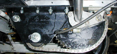
The new
dual idler bracket can now be installed. A section of the bracket
is milled out to accommodate the battery hold down nut. The bracket
has four mounting holes that align with the bolt locations for
the old idler bracket and center bearing when it was in the original
position. Be sure the bracket is exactly parallel with the car
frame and then tighten the nuts.
The original
Idler sprocket shaft used a special zerk style grease fitting
that was threaded in a very small hole in the shaft head. Our
new idler shafts are drilled and taped to 1/8” NPT for a standard
zerk fitting. Grease gun extension hoses, available in various
lengths at the local hardware store, can be threaded into this
shaft and passed through the car frame using a coupler and zerk
fitting on the outside of the car.
If you
do the same to the center bearing and all wheel bearings, you
will be able to grease the car without crawling underneath. You
will need to order a second idler shaft or have the original one
drilled and tapped for 1/8” NPT to attach the grease hose.
The top
sprocket may be installed and tightened using the lock washer
and nut provided in the kit. Install the lower sprocket, but do
not completely tighten yet as it must be moved to adjust chain
tension. I installed a flat washer under the lock washer to make
it easier to slide the sprocket in the elongated hole when adjusting
the chain.
Before
going any further, it would be a good idea to do a little inspecting.
Check the brake shaft in the area underneath the drive chain.
Many cars with loose chains will have damage to the brake shaft.
Do not operate the car if the shaft is damaged. Order a new one
or perform a proper repair on the old one but don’t let it go.
Any wear is unacceptable as it could lead to brake failure.
This next
step is optional and not required for the installation of the
axle or idler bracket, but since the axle is removed, it is much
easier to do now than it any other time. Check the springs. If
they are in poor shape. You will never get a better chance to
replace them. The same goes for the oilite guides which allow
the bearing casings to move vertically.
If you
decide to remove the springs or check the oilite guide bushings,
you must remove the bearing casings. To do so, you must drop the
aluminum channel (rail skid) that passes under both the front
and rear wheel bearing casings.
Remove
the two long bolts that pass through the guide tubes in the rear
bearing casing. Remove the two lower bolts that hold the rail
skid to the triangular shaped gusset plate just forward of the
rear axle as well as the bolts in the gusset plate just aft of
the front axle. Remove the single bolt that holds the brace to
the center of the rail skid. Now loosen, but do not remove the
nuts from the bolts that pass through the casing guide tubes on
the front axle. Don’t loosen them too much as you don’t
want the front axle to drop out of position. Do one side of the
car at a time. The rail skid should drop down enough to allow
the bearing casing and springs to be removed.
If you
open the bearing casings to check bearing condition, be careful
of the shims. Don’t loose any and make sure they go back in the
proper position. If you replace the bearings, shim them according
to Fairmonts instructions. If you need to replace the bearings
or the guides, you will have to heat the casing to get them out.
The rear springs are lighter duty than the front springs and are
not interchangeable. It is a good idea to order a set of four
of the special cylindrical nuts used to center the top of the
springs. These nuts break easily and are often replaced with improper
hardware in the field which can lead to spring failure. Reassemble
the bearing blocks and rail skids in the reverse order that they
were removed and properly tighten all hardware.
Assuming
everything is now in top condition, it is time to install the
new 4150 HT axle. Insert the axle through the bearing casing
and install in proper sequence, the thrust collars, center bearing
(turned 180 degrees from the original - the bearing cover bolts
will be on the left side) and the new “PowerLock” sprocket (Allen
screws should be facing to the right). Don’t tighten anything
yet. Do a runout on the axle to insure that it is perfectly straight
and is not being offset by a bent frame or mis-positioned bearing
casing. Drill two holes and mount the center bearing support.
I did not install the center bearing spring as my understanding
that Fairmont left them out in later cars as they were not needed.
After the center bearing is mounted, check the axle runout again
to be sure you got the center bearing properly positioned.
Before
tightening the thrust collars, make sure that exactly the same
amount of axle sticks through the bearing on each side of the
car. Tighten the thrust collar clamping bolt before tightening
the set screw. Don’t forget to safety wire the set screws Use
stainless steel wire if possible.
Carefully
position the new sprocket so that it is exactly aligned with the
forward sprocket on the transmission. The eight Allen headed
screws were gradually tightened in a crisscross pattern and then
torqued them to 12.3 foot pounds. A paint stripe applied to the
“PowerLock” and axle can be used to detect any slippage.
See the instructions and illustrations below for more information.
Since
the path for the chain is now slightly longer, I found that I
needed to add two rollers for the chain to be long enough. Start
by counting the number of rollers in your old chain. (Mine had
130) Install the old chain with the lower sprocket slid all the
way aft. Position the chain so that the masterlink would go on
the aft part of the axle sprocket and pull it as tight as possible.
With both ends of the chain on the axle sprocket, you can easily
count the number of links that need to be added.
It is
not a good idea to reuse an old chain or to add links to an existing
chain, instead, just order a new one with the proper number of
rollers and a new master link. Chains can only be cut with an
even number of rollers, so if you need three instead of two, order
an offset link. If you must cut the chain, pick up a chain cutting
tool from a local bicycle or motorcycle shop. These tools are
inexpensive and will keep you from damaging a new chain if it
is too long and needs to have links removed.
The SETOFF
article indicates that the chain in this installation should be
somewhat tighter than originally installed since the chain path
length is more constant due to the geometry of the added sprocket.
I found that if I tightened the chain until taught with the weight
of the car off the wheels, with the car on the ground, the tension
slackened slightly and seemed to me to be about right.
Check
the condition of the chain whip guard blocks. If they are worn,
new blocks and or brackets should be ordered. Reposition them
as needed for the new chain location.
Reinstall
the wheel hubs and snug them sufficiently to keep them secure.
You can fully tighten them once the car is on the ground. Don’t
forget to put the phenolic insulator washer against the hub and
the metal washer under the nut or you will be setting off every
grade crossing you pass!
Check
the condition of the wheel attachment hardware, replace as needed
and reinstall the wheels. Lower the car to the ground and
tighten the axle nuts. Install new cotter keys. Tighten all wheel
nuts and check the gauge is you did before starting. Check that
the wheels have equal distance between the inside of the flange
and the car frame. Recheck chain tension and reinspect all work
to be sure nothing has been missed.
Your car
rear axle and suspension should now be in top shape and ready
for many years of happy motoring without problems. After
a few hours of operation, recheck the torque on the PowerLock
screws. Do it again at the end of the season.
"Power Lock" Mounting and Removal
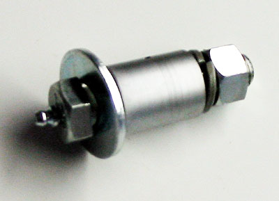
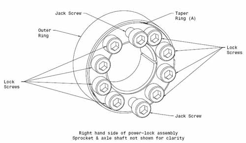
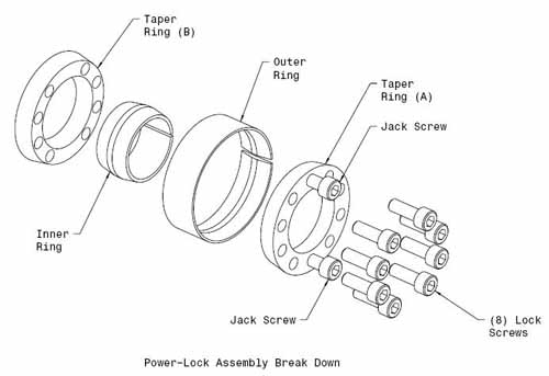
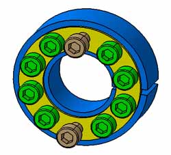
The
POWER-LOCK® is composed of five parts: taper ring (A), taper ring (B),
outer ring, inner ring, and locking screws. Locking is achieved by
tightening the screws.
|
 |
Mounting
1) Clean and lightly oil or grease the shaft and
hub bore. (Do not use oil or grease containing molybdenum disulphide.)
2) Remove the locking bolts from the POWER-LOCK®
and clean and lightly oil, or grease the contact surfaces. Threads and
seats of the locking screws must also be sufficiently lubricated.
3) Slip the POWER-LOCK and hub onto the shaft,
tighten the locking screws by hand until a slight positive contact is
felt, and set them at the predetermined position, just as you would
tighten lug bolts on a car wheel. When it is difficult to slip on,
loosen the screws. (Do not strike with a hammer.)
4) Next, determine the relative positioning
between the hub and shaft (on the circumference and shaft line), and
tighten the four screws positioned diagonally with 1/4 of the required
tightening torque. Proceed to tighten the remaining screws in the same
manner.
5) Increase the tightening torque to half of 12.3
foot pounds and tighten the screws in the same way as in Step 4.
6) Increase tightening torque to 12.3 foot pounds and tighten the screws.
7) Check the tightening torque of the locking screws in sequence. This completes the mounting procedure
NOTE:
There are ten holes in taper ring (A) with eight of them being lock
screws The other two are jack screws. The jack screws are only
required for removal of the power-lock hub either by pulling on the
heads or turning them in against inner taper ring (B). |
 |
Removal
1) Make sure that no torque or thrust is being
applied to the shaft and hub. When shaft and hub are heavy, take them
off the shaft carefully.
2) After completing Step 1, loosen the locking screws. (No definite sequence is required.)
3) If the POWER-LOCK is still locked even after
loosening the screws, insert screws into the jack screw holes (see photo
below) and screw them in until it unlocks.
|
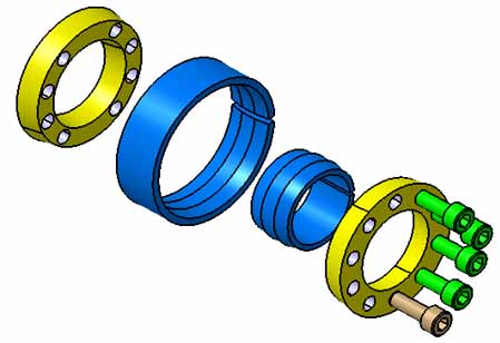 |
The drawings at left are courtesy of Wayne Schlueter and Illustrate in color the Power-Lock Assembly.
Thanks, Wayne. |
  |
|
|